Documents
Device Wiring
The interface layout of the Cloud Integrated Processor is shown below:
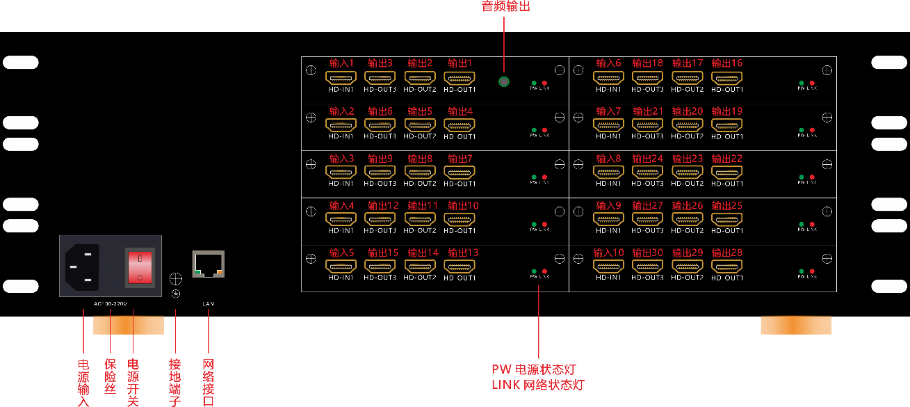
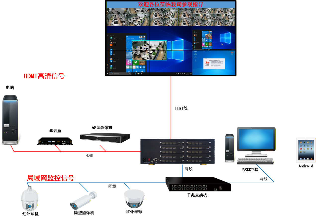
Device wiring top view (this diagram assumes wiring with decoding; which devices are actually connected depends on the site).
LED indicators: the PW power LED steady on means power is normal; the LINK network port LED blinks when data is transmitted. If it never lights, the network cable is not connected properly or the network is unreachable.
Network environment requirements: a gigabit switch is recommended and network cables must be Cat5e or better; the commissioning PC and the processor main control IP must be on the same subnet (see Chapter 2).
Did this page help you?One line of feedback helps us keep the steps accurate.